8 To 1 Multiplexer - Multiplexer and demultiplexer applications.ppsx 3 / 8:1 multiplexer | design and implementation simple method to design 8:1 multiplexer #multiplexer #digitallogic.. For the combination of a selection input, the data line is connected to the output line. The selection of one of the n inputs is done by the select pins. To design 8 to 1 multiplexer we need three 4 to 1 multiplexers. Some multiplexers perform both multiplexing and demultiplexing operations. Working of 8 to 1.
4x1 multiplexer has four data inputs i3, i2, i1 & i0, two selection lines s1 & s0 and one output y. A simple explanation of a multiplexer. Spelled sometimes as multiplexor), also known as a data selector, is a device that selects between several analog or digital input signals and forwards the selected input to a single output line. Multiplexer is one of the basic building units of a computer system which in principle allows sharing of a common line by more than one input lines. In this video, i have explained 8 to 1 multiplexer by following outlines:
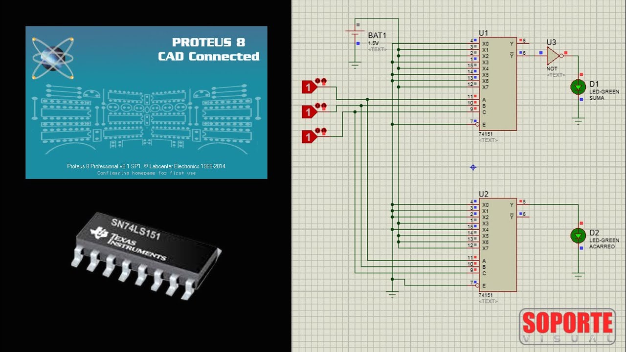
Sumador Completo con 2 Multiplexores 74151 (8x1) - Proteus ... from i.ytimg.com Working of 8 to 1. Multiplexers are not limited to just switching a number of different input lines or channels to one common single output. The selection of a particular input line is controlled by a group of selection lines. 8 to 1 multiplexer hdl verilog code. If you want multiple sources of data to share a single, common data line, you'd use a multiplexer to run them into that line. A multiplexer (or mux) is a common digital circuit used to mix a lot of signals into just one. One stop for your rf and wireless need. In this video, i have explained 8 to 1 multiplexer with following timecodes:
The circuit shown below is an 8*1 multiplexer.
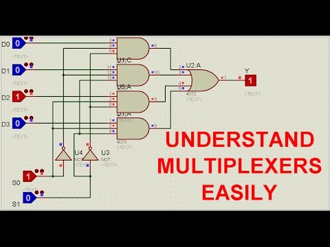
Please see the code from the link below. A 2 to 1 line multiplexer is shown in figure below, each 2 input lines a to b is applied to one input of an and gate. On the other hand, these problems can keep on giving when it comes to their ability to teach us things. An 8 * 1 multiplexer has inputs a, b, and c connected to the selection inputs s2 , s1, and s0, respectively. The block diagram of 4x1 multiplexer is shown in the following figure. Multiplexer is a combinational circuit that selects binary information from one of many inputs lines and directs it to a single output line. The two outputs are active low and active high outputs. Not the answer you're looking for? In this video, i have explained 8 to 1 multiplexer by following outlines: Here 8 and gates are used to enroute 8 inputs to output with or gates and this all eight and gates are selected by 3:8 decoder inputs which are explained in function table in diagram. Был ли этот ответ полезен? Selection lines s are decoded to select a particular and gate. With the given data the complete realisation of 8:1 multiplexer is shown in following logic diagram.
Realize the multiplexer using logic gates. One stop for your rf and wireless need. In this video, i have explained 8 to 1 multiplexer with following timecodes: Selection lines s are decoded to select a particular and gate. For the combination of a selection input, the data line is connected to the output line.
4 to 1 line multiplexer - YouTube from i.ytimg.com The selection of a particular input line is controlled by a group of selection lines. A multiplexer (mux) is a digital switch which connects data from one of n sources to the output. A simple explanation of a multiplexer. These quality 8 to 1 multiplexer available on alibaba.com offers the buyer the ability to stream and source for media via the internet. This is why, multiplexers are also called as 'many to one' combinational circuits. This video describes the implementation of 8:1 multiplexer using a logic function. .analog multiplexer multiplexers digital multiplexer demultiplexer multiplexer ic multiplexer circuit multiplexer chip analogue multiplexer signal hello friends, in this video i have explained how to implement logic function using 8 to 1 multiplexer in simple language. See the circuit diagram & truth tables for 2 to 1, 4 to 1, 8 to 1, and arduino multiplexers.
This video describes the implementation of 8:1 multiplexer using a logic function.
Please see the code from the link below. Spelled sometimes as multiplexor), also known as a data selector, is a device that selects between several analog or digital input signals and forwards the selected input to a single output line. More important is what is inside. An 8 * 1 multiplexer has inputs a, b, and c connected to the selection inputs s2 , s1, and s0, respectively. This video describes the implementation of 8:1 multiplexer using a logic function. The selection of one of the n inputs is done by the select pins. 4x1 multiplexer has four data inputs i3, i2, i1 & i0, two selection lines s1 & s0 and one output y. One of these 4 inputs will be connected to the output based on the combination of inputs present at these two selection lines. A multiplexer (or mux) is a common digital circuit used to mix a lot of signals into just one. Multiplexer is one of the basic building units of a computer system which in principle allows sharing of a common line by more than one input lines. This page of verilog sourcecode covers hdl code for 8 to 1 multiplexer using verilog. To design 8 to 1 multiplexer we need three 4 to 1 multiplexers. A 2^n:1 multiplexer has 2^n input lines, n select lines, and a single output line.
Share this video with your. Multiplexers are not limited to just switching a number of different input lines or channels to one common single output. Realize the multiplexer using logic gates. Был ли этот ответ полезен? Name and function multiplexer inputs multiplexer output complementary multiplexer output enable input (active low) ground (0 v) select inputs positive supply fig.6 waveforms showing the multiplexer input (in) to outputs (y and y) propagation delays and the output transition times.
Full adder using multiplexer - YouTube from i.ytimg.com The selection of a particular input line is controlled by a group of selection lines. The selection of one of the n inputs is done by the select pins. On the one hand, some logic problems never seem to go away. Name and function multiplexer inputs multiplexer output complementary multiplexer output enable input (active low) ground (0 v) select inputs positive supply fig.6 waveforms showing the multiplexer input (in) to outputs (y and y) propagation delays and the output transition times. A 2^n:1 multiplexer has 2^n input lines, n select lines, and a single output line. 8 to 1 multiplexer hdl verilog code. One of these 4 inputs will be connected to the output based on the combination of inputs present at these two selection lines. The show me an error that i search it and i found that is from verilog language and i don't understand why?
A multiplexer (mux) is a digital switch which connects data from one of n sources to the output.
The selection of a particular input line is controlled by a group of selection lines. I check again and again my code and i dont find any mistake. On the other hand, these problems can keep on giving when it comes to their ability to teach us things. Vhdl code for mux(multiplexer) and demux(demultiplexer). To realize the following boolean function f(a,b,c) = σm(1, 2, 4). I try to do in eda playground platform a code for 8x1 multiplexer put something is going wrong. Hence i disagree with your first sentence: A multiplexer (or mux) is a common digital circuit used to mix a lot of signals into just one. The show me an error that i search it and i found that is from verilog language and i don't understand why? Был ли этот ответ полезен? Name and function multiplexer inputs multiplexer output complementary multiplexer output enable input (active low) ground (0 v) select inputs positive supply fig.6 waveforms showing the multiplexer input (in) to outputs (y and y) propagation delays and the output transition times. The selection of one of the n inputs is done by the select pins. Here 8 and gates are used to enroute 8 inputs to output with or gates and this all eight and gates are selected by 3:8 decoder inputs which are explained in function table in diagram.
You have just read the article entitled 8 To 1 Multiplexer - Multiplexer and demultiplexer applications.ppsx 3 / 8:1 multiplexer | design and implementation simple method to design 8:1 multiplexer #multiplexer #digitallogic.. You can also bookmark this page with the URL : https://calder-dd.blogspot.com/2021/05/8-to-1-multiplexer-multiplexer-and.html
Share Awesome
Belum ada Komentar untuk "8 To 1 Multiplexer - Multiplexer and demultiplexer applications.ppsx 3 / 8:1 multiplexer | design and implementation simple method to design 8:1 multiplexer #multiplexer #digitallogic."

Belum ada Komentar untuk "8 To 1 Multiplexer - Multiplexer and demultiplexer applications.ppsx 3 / 8:1 multiplexer | design and implementation simple method to design 8:1 multiplexer #multiplexer #digitallogic."
Posting Komentar